 photo: E. Traber - collection of Sébastien Kieffer 2018 |
CFTR 62029  DRS6-4-660 c/n 72926, b/d 12/1946 - built for the French Supply Council as #040-DA-29 - became SNCF 62029 - to Chemin de Fer Touristique du Rhin in 1983 |
 photo by: Sébastien Kieffer - CFTR Shops - Feb. 22, 2025 |
|
 Sébastien |
|
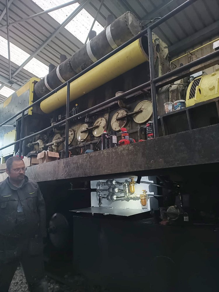
| "In july of 2025, the tank which was badly mounted unter the chassis of the loco, needed some further screws to be added to stabilize it. When this was done, it was connected to the original pump. In august, the first tests with 120V showed that even if the electric motor got current and drove the pump, the suction was insufficient. Another pump saved at Gray in 2019 was used instead and tested. The result was worse, the pump got very noisy and the suction was even worse. We had another pump from the same type from more the 30 years ago, from the depot in Strasbourg. It was also hydraulically and electrically connected but no chance. That's why I took the decision to realize a complete new module for pressure generation, including non-return valves before and after it and pre-filter before the pumps. After having considered possible Bosch Pumps and as there was a need for a volume flow of 660 l/min and a pressure of at least 1.8 bar at the High-Pressure Bosch pumps, I could compute that 3 pumps in parallel were necessary, 1 pump can be considered necessary for a power of about 250HP. There was necessity to also modify the electrical circuit as the pumps are 12V pumps for automotive application and there was this wish not to change the switch in the cab (which is under 120V)." |
|
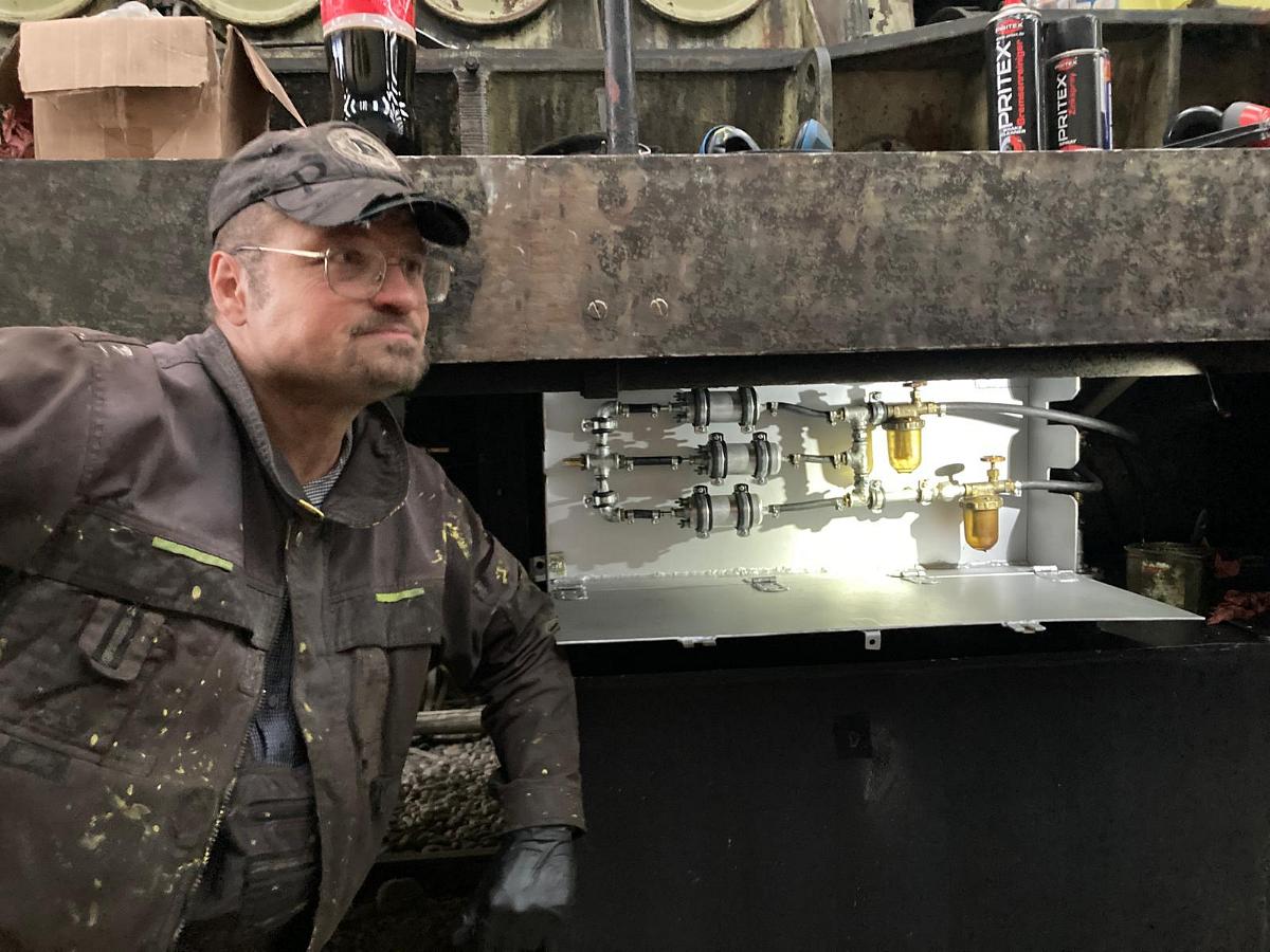
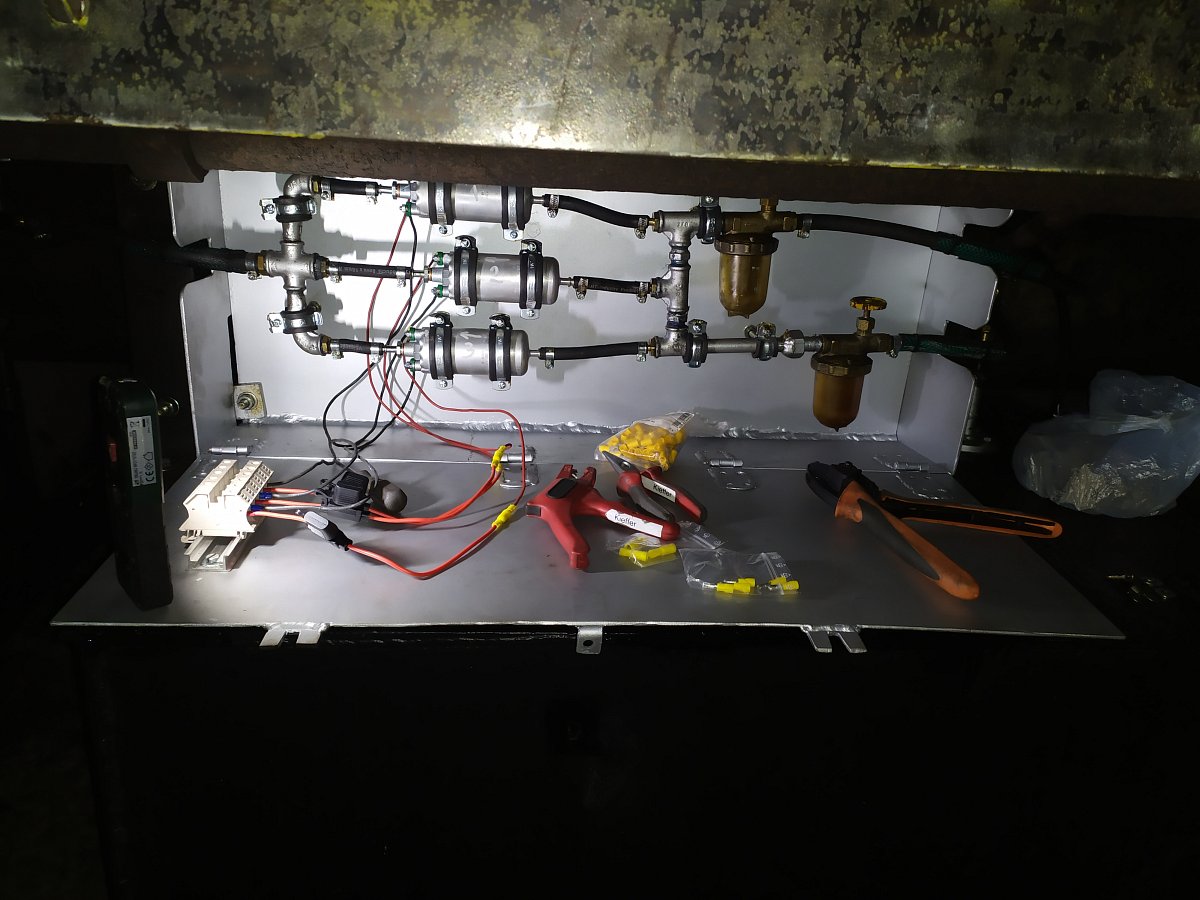
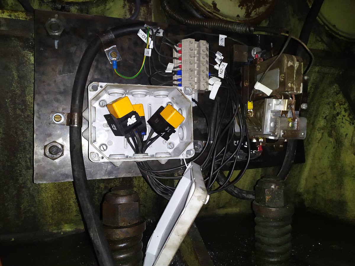
| "The ensemble now is working using a relay/interlock normally which was originally needed to close the circuit of external excitation of the exciter YG40 and that we had as a spare part. This relay is used in a low-voltage circuit of 12V with automotive relays that turn the pumps on and off. The whole box in which the pumps have been mounted had to be completely welded and adapted to the location, under the chassis, as close as possible from the tank to avoid potential cavitation and make sure that there will be no trouble with suction. Also the pipes from tank to the filter along the engine had to be build and mounted. The electrical part has not been located under the chassis to be protected from dust and dirt and is mounted where the pump originally was." |

|

|

|

|

|

|

|
 YG40 (combination auxiliary generator-exciter) seen on top of the main generator |
 The interlock for closing the circuit for separate excitation of the exciter on the YG40 (combination auxiliary generator-exciter) |
 The interlock before cleaning |
 engine viewed from the manifold side showing the location of the cooling passages between the cylinderhead and the engine block |
 the cooling passages connector assembly bolted in place |


|
|
"As you surely know, the Westinghouse YG40C is a combination of the auxiliary generator and the exciter. The first has 4 brushes and has been already cleaned and repaired it in April, as already reported (see below). Now in this month of November and after having spent a lot on time on our GE #4036 locomotive, I had time to care for the exciter. This one is also only to be serviced when the complete YG40C is disassembled from the loco. In fact, the exciter has more brushes than the auxiliary generator and its function principle is totally different as it is primarly meant to excite the main 480 Generator. The exciter itself has 6 poles windings for its own electrical excitation. 4 of them have a unique winding per pole. The windings of each of these 4 poles are connected in series and are fed by an external circuit (Positive). As 4 poles are involved in this circuit, current level here does not need to be high (approx. max 7A) and consequently it is possible to fine tune the output of the exciter anchor very precisely which mainly controls the output of the main generator. This circuit is fed by the auxiliary generator and involves for example the carbonstat, a system which is able to limit the current in the case the prime mover should be overloaded. The next 2 poles consist each of 2 concentric windings we can call "A" and "B". Winding A from pole 1 is connected in series with winding A from pole 2 and winding B from pole 1 is connected in series with winding of pole 2. Here we have 2 separated circuits, insulated each from the other. These Windings A are fed by the anchor of the exciter itself through a calibrated resistance of 9.6 Ohms. It is the so-called shunt excitation. (Positive) The Windings B are fed by the anchor of the main generator (i.e. with traction current) and are connected in series with the commutation poles of it. They produce a field in the opposite direction of both other circuits (negative). 30 and more years of (perhaps too much) greasing and absence of maintenance (As it is impossible to access properly to all 6 brushes when the YG40 is not disassembled from the locomotive) have led to the situation that the brushes were not working properly anymore. Pressure exterted on the collector was not correct, leading either to a high wear of the carbon brushes (when these were blocked in their slide bar) and very dirty collector or to flashes when the pressure was not high enough. The disassembling and reassembling of the brush holders was very "sporty" because of some mistakes in the construction of the assembly. But now the brush holders and the collector are bright and clean and everything is reassembled again. :-)" |

|

|

|


|

|

|

|
|
Auxiliary generator mounted on top of main generator 
|

|

|

|

|

|

|

|

|

|

|

|

|

|

|

|

|

|

|

|


